Passer au contenu
Table des matières
Introduction
The wire gauge inside a USB‑C cable dictates how much resistance you get, how much voltage you lose under load, how warm the cable runs, and—indirectly—how reliably high‑speed data moves through. In short: AWG isn’t a marketing footnote; it’s a performance constraint you can quantify.
Who should read this: procurement and supply‑chain teams that need PO terms and pass/fail thresholds; supplier‑quality engineers who plan sampling and acceptance tests; and hardware engineers who care about impedance, shielding, and voltage‑drop math.
What you’ll get: practical AWG‑by‑length/current guidance, a clear split between PD 3.0 (up to 100 W) and PD 3.1/EPR (up to 240 W), what E‑markers must report, and step‑by‑step verification tests you can run in your lab.
Key Takeaways: USB cable AWG, PD, and Data Rules
Choose gauge by current and length, then verify with a 4‑wire voltage‑drop test. As guidance, 1 m at 3 A prefers 22–24 AWG, 1 m at 5 A often needs ~20–21 AWG, and 2 m at 5 A typically requires 20 AWG with thermal checks. Any cable used at 5 A must be electronically marked; PD 3.1 EPR extends power to 28/36/48 V (up to 240 W) and expects a 5 A, high‑voltage‑rated, E‑marked cable. Data integrity hinges on impedance control and shielding—hold SuperSpeed/USB4 pairs near 85–90 Ω with individual pair shields—and confirm margin with eye diagrams when risk is high. Buy with tests, not promises: specify copper, AWG by current/length, E‑marker fields, and acceptance tests (continuity, DCR, ΔV under load, E‑marker dump, Hi‑Pot), and confirm USB‑IF certification when required.
Pro Tips: Want to understand the specific requirements and details of USB-IF like the experts? Read our Ultimate Guide to USB-IF Certified Cables (2025 Edition) and you too can gain a deep understanding of USB cable industry standards, just like us.
AWG Basics

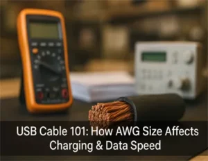
What is USB Cable AWG
American Wire Gauge (AWG) numbers run counterintuitively: a smaller number means a thicker conductor with lower resistance. USB‑C power (VBUS/GND) conductors are typically multi‑strand copper; SuperSpeed/USB4 data pairs are separate twisted pairs, usually with individual shields and an overall braid/foil. For procurement, the AWG callout on the datasheet should distinguish power versus data conductors, since they rarely share the same gauge.
Resistance and Voltage Drop
Conductor resistance rises as gauge gets thinner. Representative copper values at ~20 °C:
AWG | Approx. Resistance (Ω/m) |
20 | 0.033 |
22 | 0.053 |
24 | 0.084 |
26 | 0.133 |
28 | 0.212 |
Round‑trip voltage drop across a cable is roughly ΔV ≈ 2 × I × R_per_meter × length. Exemple: 1 m, 24 AWG at 3 A → ΔV ≈ 2 × 3 × 0.084 × 1 = 0.504 V. Many devices budget only a few hundred millivolts, so this simple math often pushes you to thicker wire or shorter length. For elevated temperatures, add margin because copper resistance increases with heat.
For engineering background on Ω/m values, see the publisher’s wire‑gauge table summarized in the widely referenced PowerStream page in the Sources section below.
Length and Heat Limits
Longer cables have higher total resistance, so they drop more voltage and dissipate more heat (I²R). Two practical limits emerge: you either exceed your voltage‑drop budget at the sink, or you reach an uncomfortable temperature rise in the cable bundle. Either way, AWG and length are a trade‑space—don’t spec one without the other, and always validate under the intended current.
USB Cable Charging and PD Power

3A vs 5A USB Cables
USB Type‑C allows up to 3 A on cables without an E‑marker, while 5 A cables must be electronically marked so sources and sinks can discover the current capability. Under PD 3.0, 20 V × 5 A reaches 100 W. PD 3.1 adds Extended Power Range (EPR) with fixed 28 V, 36 V, and 48 V profiles up to 240 W. EPR operation relies on a 5 A, high‑voltage‑rated, E‑marked cable.
E-marker Compliance
An E‑marker responds during Discover Identity and reports fields such as current capability (3 A vs 5 A), cable type (passive/active), speed class (USB2 only, SuperSpeed, USB4), indicated length, and whether it supports higher‑voltage EPR operation. According to the USB‑IF’s published functional test material, these items are exercised during compliance and allow systems to negotiate appropriate limits.
Spec by Length & Current
Use the math from AWG basics to choose a starting gauge, then verify. As engineering guidance—not a USB‑IF prescription—here’s how to translate current and length into a starting gauge and acceptance logic:
For 0.3–0.5 m at up to 3 A, 26–28 AWG power can pass if your voltage‑drop budget allows; measure to confirm. At 1.0 m and 3 A, prefer 22–24 AWG and target ≤0.318–0.504 V drop. At 1.0 m and 5 A, start at 20–21 AWG and verify temperature rise and ΔV. At 2.0 m, use ~20–22 AWG for 3 A; for 5 A, start at 20 AWG and validate both drop and heat. Worked example: 1 m, 20 AWG at 5 A with 0.033 Ω/m yields ΔV ≈ 2 × 5 × 0.033 × 1 = 0.33 V, which is a reasonable screen for many 20 V and 28–48 V rails.
Below is a quick PD 3.0 vs PD 3.1/EPR summary to anchor procurement language.
Item | PD 3.0 (SPR) | PD 3.1 (EPR) |
Max voltage | 20 V | 28 V, 36 V, 48 V |
Max current | Up to 5 A | 5 A |
Max power | 100 W | Up to 240 W |
Cable requirement | 3A cables: no E‑marker; 5A cables: E‑marker required | 5A, E‑marked, high‑voltage‑rated; participates in EPR negotiation |
Procurement note | Confirm current capability via E‑marker for 5 A cables | Confirm EPR indicators and voltage rating via E‑marker and PD trace |
For authoritative context on EPR power levels, see Texas Instruments’ 240 W PD 3.1 reference design guide and Renesas’ PD 3.1 EPR application notes cited in Sources.
USB Cable Data Performance

USB 2.0 vs USB 3.x
USB 2.0 uses a single differential pair (D+/D−) that industry practice centers near ~90 Ω differential. SuperSpeed and USB4 add separate high‑speed differential pairs with tighter impedance control and per‑pair shielding. USB4 design materials commonly target around 85 Ω ±9 Ω for high‑speed paths through plugs and cables. Impedance mismatches and poor shielding erode eye margin, so treat data construction as its own spec independent of power AWG.
USB 3.x vs USB4
USB 3.x (SuperSpeed) and USB4 can look identical on the outside, but they stress cables differently. For procurement and supplier-quality teams, the practical takeaway is that “USB 10/20 Gbps” and “USB4” aren’t interchangeable claims—you should expect different verification evidence and, in some cases, different cable constructions.
What Changes with USB4
USB 3.x is a point-to-point SuperSpeed link that typically uses one set of high-speed differential pairs (with encoding and link training defined per generation). USB4 is built on a tunneling architecture and, in the common two-lane case, can use two high-speed lanes per direction. That pushes tighter requirements around insertion loss, crosstalk, and lane-to-lane skew across the full cable-and-connector path.
Passive vs Active Cables Matters More at USB4 Rates
At shorter lengths, a well-built passive cable can meet USB 3.x and some USB4 use cases. As length increases, USB4 performance is more likely to depend on an active cable (redrivers/retimers in the cable ends) to recover signal margin. That’s why a USB4-capable cable often has clearer constraints around maximum supported length for a given speed class.
Don’t Accept “USB4” Without the Right E-marker Fields
For Type-C full-featured cables, the E-marker can advertise the cable’s supported data capability (for example, whether it’s USB2-only, SuperSpeed, or USB4-class). As a buying rule, treat the E-marker readout as the first pass/fail gate: if the cable is marketed as USB4 and the marker doesn’t report a USB4-capable speed class, fail it before you spend time on eye-margin work.
Acceptance Note You Can Put in a PO
Require (1) an E-marker dump that matches the datasheet speed class, cable type (passive/active), and indicated length; and (2) certification evidence when the USB-IF logo claim is important for your program. Use lab characterization (fixtures + compliance-style tests) selectively for high-risk builds like longer cables, tight EMI environments, or USB4 hosts with known margin sensitivity.
Shielding and Impedance
For SuperSpeed/USB4 cables, require individually shielded twisted pairs for each TX/RX lane, an overall braid/foil for EMI, and documented pair‑to‑pair skew. Keep the assembly’s differential impedance within the target band to reduce reflections and jitter. A neat way to think about it: power AWG decides whether your sink sees enough volts; impedance and shielding decide whether your receiver sees a clean eye.
Testing Eye Diagrams
At USB 2.0, an eye diagram mask test verifies high‑speed signal quality. For SuperSpeed/USB4, compliance setups measure at defined test points to check mask hits, jitter, and loss. In practice, most procurement teams don’t run full compliance; instead, they rely on vendor certification plus targeted screening with fixtures and a protocol analyzer when risk is high.
Contextual, non‑promotional verification workflow: in a lab, pair a programmable load and 4‑wire sense leads (to characterize cable DCR and voltage drop) with a PD analyzer that can sniff negotiation, read the cable’s E‑marker VDOs (confirming 5 A and speed class), and capture traces during EPR entry. This combined view quickly surfaces mismatches such as a “5 A” label on a cable whose marker reports only 3 A, or a SuperSpeed claim with poor shielding that collapses eye margin.
For impedance targets and high‑speed guidance, see the USB‑IF’s USB4 plug high‑speed requirements white paper and related cable compliance materials linked in Sources.
3 Tips for USB Cable Supplier Sourcing
Conductor and Materials
Specify oxygen‑free copper or equivalent for power and data conductors. Call out AWG separately for power (VBUS/GND) and data pairs. Require tin or appropriate plating on conductors as needed, adequate drain wires for shields, and a flame/smoke jacket that meets your regulatory region. Avoid copper‑clad steel for power.
Connectors and Durability
Set mating‑cycle durability targets (e.g., ≥10,000 insertions for USB‑C) and require strain‑relief designs that limit conductor flex at the plug exit. For ruggedized applications, add pull‑force and bend‑radius criteria.
Compliance Checklist

Translate your spec into acceptance items: copper and gauge, shielding structure, connector durability, E‑marker fields for 5 A/EPR, USB‑IF certification (TID), and the exact bench tests your QA will run. Use the graphic below as a one‑page reminder.
To confirm certification, use the public USB‑IF Product Search once you have a model name and vendor ID.
USB Cable Verification Tests

Voltage-drop Under Load
Setup: Source a PD profile that matches your use case (e.g., 20 V @ 3 A or 5 A; for EPR, 28/36/48 V @ 5 A). Place a programmable load at the sink side. Use four‑wire (Kelvin) sense to measure V_source at the upstream plug and V_sink at the downstream plug with minimal lead error. Record ΔV = V_source – V_sink at rated current and compute equivalent DCR = ΔV / I ÷ 2 ÷ length.
Acceptance guidance: for a 1 m cable at 3 A, target ≤0.318–0.504 V drop; at 5 A over 1 m, ≤0.33–0.42 V is a practical screen depending on device headroom. If your device is sensitive at 5 V rails, be stricter.
E-marker Readout
Procedure: Power VCONN and issue Discover Identity, then parse Cable VDOs. Confirm that current capability is 5 A for any cable marketed for 5 A or EPR use; verify speed class and cable type match the datasheet (USB2‑only vs SuperSpeed/USB4; passive vs active); check that indicated length is plausible for the build; and for EPR, look for higher‑voltage suitability indicators and verify in a PD trace that negotiation reaches the requested EPR profile. Any mismatch between printed claims and marker fields is a procurement fail. The USB‑IF’s functional test documentation provides the context for these exchanges; analyzer vendors also demonstrate typical readouts.
Continuity and Hi-Pot
Verify end‑to‑end connections for all pins and measure power‑conductor resistance in milliohms. Require no unintended continuity between unrelated nets and a screening insulation value around ≥100 MΩ at 250 VDC. Apply an appropriate dielectric withstand test between power and signal groups (for example, ~1500 VAC for 60 s with no breakdown) according to the supplier’s CTF and safety policy. Document the exact voltages, dwell times, and leakage limits in the PO.
About Cablink

Cablink is a procurement-focused USB‑C cable supplier that’s built around the same theme as this guide: buy with measurable requirements, then verify. If you need cables that are consistent lot-to-lot—and you want documentation your supplier-quality team can actually file – Cablink is structured to support that workflow.
Why teams choose Cablink
- Specify copper conductors, AWG by length/current, shielding structure, connector durability, and E‑marker requirements in the PO
- Test resistance and voltage drop under rated load with 4‑wire sense; read and archive the E‑marker fields; run continuity and Hi‑Pot screening per the supplier’s CTF
- Certification-led sourcing: Cablink positions itself as a USB‑IF certified USB cable manufacturer. For programs where logo compliance and consistent interoperability matter, that certification trail can reduce qualification churn. (As with any supplier claim, it’s still smart to confirm specific models in the USB‑IF Product Search.)
- Acceptance and audit readiness: Support for practical incoming inspection expectations such as PD negotiation checks (including PD 3.1 EPR scenarios), resistance/voltage-drop measurements, and batch testing records.
- Traceability: Lot and serial traceability options so you can tie field issues back to a specific build and corrective-action record.
To learn more about Cablink’s background and manufacturing approach, see Cablink’s company overview. For cable categories and product coverage, browse Cablink USB‑C cables.
Conclusion
The bottom line is simple: thicker conductors and better shielding make cables perform predictably, but you shouldn’t guess—measure. Choose AWG by current and length, confirm the E‑marker for any 5 A or EPR scenario, and verify data integrity with impedance‑aware construction and, when risk is high, basic eye checks.
Action list for buyers and SQE teams:
- Specify copper conductors, AWG by length/current, shielding structure, connector durability, and E‑marker requirements in the PO
- Test resistance and voltage drop under rated load with 4‑wire sense; read and archive the E‑marker fields; run continuity and Hi‑Pot screening per the supplier’s CTF
- Check the supplier’s USB‑IF certification via the Product Search and log TIDs in the lot record
FAQ
Does a lower AWG number always charge faster?
Not always. A lower AWG (thicker copper) reduces resistance, which usually reduces voltage drop and heat at a given current—so it can help charging performance. But charging speed still depends on what your charger and device negotiate (USB PD), the device’s own charging limits, and whether the cable is correctly built and marked.
What AWG should I look for in a 1 m USB-C cable for 3 A or 5 A?
As a practical starting point (engineering guidance), many 1 m cables target roughly 22–24 AWG for 3 A et 20–21 AWG for 5 A on the power conductors (VBUS and GND). The only reliable way to confirm is to measure voltage drop under load, because strand count, copper quality, crimps, and connector resistance can dominate the result.
What’s the difference between a 3 A cable and a 5 A cable?
In USB-C terms, a 3 A cable is allowed to carry up to 3 A without needing an electronic ID chip. A 5 A cable is designed for higher current and must be electronically marked so the source and sink can safely discover it’s allowed to draw 5 A.
You’ll often see 5 A cables use thicker power conductors (lower AWG), but the defining rule is the E-marker advertising 5 A capability, not the jacket printing.
What is an E-marker, in plain English?
An E-marker (electronically marked cable) is a tiny chip inside certain USB-C cables that reports the cable’s capabilities during USB-C discovery. Think of it like a “spec label the devices can read.” It can indicate items like current capability (3 A vs 5 A), whether the cable supports certain data speeds, whether it’s passive or active, and (for some cables) whether it’s suitable for higher-voltage EPR use.
Can I use a 5 A / 240 W cable with a normal 60 W charger?
Yes. USB-C is designed to be backward compatible: a higher-rated cable can be used at lower power. In that case, the system will negotiate only what the charger and device support. You won’t “force” 240 W just by plugging in a bigger cable.
Does USB PD 3.1 EPR require a special cable?
Yes. EPR (Extended Power Range) is the part of USB PD 3.1 that enables 28 V, 36 V, and 48 V profiles (up to 240 W at 5 A). In practice, EPR assumes a 5 A, electronically marked, higher-voltage-rated cable and relies on correct cable identity and PD negotiation. If the cable isn’t EPR-suitable, systems should fall back to lower power.
Why does my device charge slowly even with a “100 W” cable?
Common causes include:
- The charger is negotiating a lower PD profile than you expect (for example, 9 V or 15 V instead of 20 V)
- The cable label doesn’t match the E-marker (a “5 A” jacket print but a 3 A marker)
- Excess voltage drop from thin conductors, long length, or high connector resistance
- The device is thermally limiting or has its own charging cap
A quick way to isolate the cable is a voltage-drop test at the target current plus an E-marker readout.
Is a USB4 cable automatically the best for charging?
Not necessarily. USB4 branding is about data performance, not power loss. Some USB4 cables are excellent for both, but charging performance still comes down to power-conductor resistance and correct 5 A/EPR marking where needed. It’s completely possible to have a great USB4 data cable that’s only average for voltage drop at high current, especially at longer lengths.
What’s the simplest at-home check for cable quality?
If you don’t have lab tools, the simplest practical check is comparative:
- Use the same charger and device
- Try two cables of the same length
- Feel for unusual heating at the plugs during high-power charging
- If your device shows charging power/current, compare readings
For procurement or QA decisions, though, you’ll eventually want objective numbers: milliohm-level resistance and voltage drop at rated current.
What does “USB-IF certified” mean, and should I require it?
“USB-IF certified” generally means the product has passed relevant USB-IF compliance testing and is listed with a certification ID (often called a TID). For many consumer scenarios it’s optional, but for enterprise procurement, regulated environments, or large-volume deployments, requiring certification is a clean way to reduce risk—especially when you need consistent behavior across PD negotiation, E-marker reporting, and high-speed data modes.